


Post by 3DMS on Dec 18, 2015 9:57:02 GMT
This probe is used on many modern 3D printers with metalic heatbeds for Autoleveling purpose.
It's cheap and robust in design and can handle the heat of the heatbeds.
It's always/mostly provided as a 6-36V version wich is not compatible with standard Microcontroler boards requiring 3.3-5V input voltage (for most 8Bit microcontrolerurs such as Atmega 2560).
If you try to use 5V input voltage the probe won't work at all.
To asses this constraint, people are powering the probe using the 12V input voltage.
To make the output compatible with TTL (0-5V) input level voltage, the cheap way to do it is to solder a resistor bridge as shown on this picture:

(source: forums.reprap.org/read.php?1,430371,596450)
As a reminder, on the probe itself you should find a wiring diagram:

With brown wire = +12V input
Black wire = Signal Ouput
Blue wire = 0V (Ground)
From the Previous Schematic
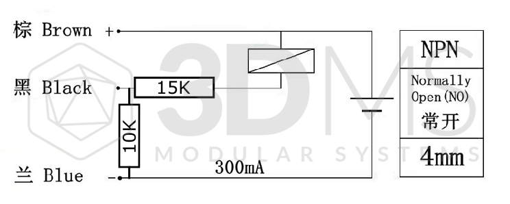
If you are using the Probe wiring diagram, you will need to invert the resistor bridge:
The 10K resistor will be placed on the very left side
The 15K resistor will be placed on the middle of the schematic
The final wiring diagram should look like this one:
Alternatives:
Instead of the 10Kohm resistor you can also use a 9Kohm resistor, if you keep the 15K resistor.This should give you something close to 4V output
You can also use a 20K resistor instead of 15K resistor, if you keep the 10K resistor. This should give you a voltag close to 4V output also.
Important Note:
The probe signal output voltage is slightly lower than the input voltage. So if you apply 12V input voltage you will have a signal output voltage lower than 12V.
Consider this if using the alternative solutions as they might not work that well.
It's cheap and robust in design and can handle the heat of the heatbeds.
It's always/mostly provided as a 6-36V version wich is not compatible with standard Microcontroler boards requiring 3.3-5V input voltage (for most 8Bit microcontrolerurs such as Atmega 2560).
If you try to use 5V input voltage the probe won't work at all.
To asses this constraint, people are powering the probe using the 12V input voltage.
To make the output compatible with TTL (0-5V) input level voltage, the cheap way to do it is to solder a resistor bridge as shown on this picture:
(source: forums.reprap.org/read.php?1,430371,596450)
As a reminder, on the probe itself you should find a wiring diagram:
With brown wire = +12V input
Black wire = Signal Ouput
Blue wire = 0V (Ground)
From the Previous Schematic
- Vin = Brown wire
- Sig = Black wire
- Vout = Blue Wire
If you are using the Probe wiring diagram, you will need to invert the resistor bridge:
The 10K resistor will be placed on the very left side
The 15K resistor will be placed on the middle of the schematic
The final wiring diagram should look like this one:
Alternatives:
Instead of the 10Kohm resistor you can also use a 9Kohm resistor, if you keep the 15K resistor.This should give you something close to 4V output
You can also use a 20K resistor instead of 15K resistor, if you keep the 10K resistor. This should give you a voltag close to 4V output also.
Important Note:
The probe signal output voltage is slightly lower than the input voltage. So if you apply 12V input voltage you will have a signal output voltage lower than 12V.
Consider this if using the alternative solutions as they might not work that well.